68k Retro PC project

I have always wanted to build a retro PC from basic parts. Now I have started with a 68k project in several phases.

The PC will have a basic north-bridge, south-bridge architecture with high speed interfaces, CPU, memory and graphics in the north-bridge part and slower interfaces like keybord, mouse, mass storage, network, joysticks, etc on the south-bridge part, that may be on the same, on a separate FPGA, or a supporting ARM-processor.

The end goal is to use a 68030 (I have a stash of about 140 NOS ‘030s) and add as much DDR2 memory as possible, and have as large graphics resolution and color depth as memory bandwidth can support, along with hardware accelerated graphics drawing. By dividing the project in several phases I can keep testing concepts as long as I like 😀

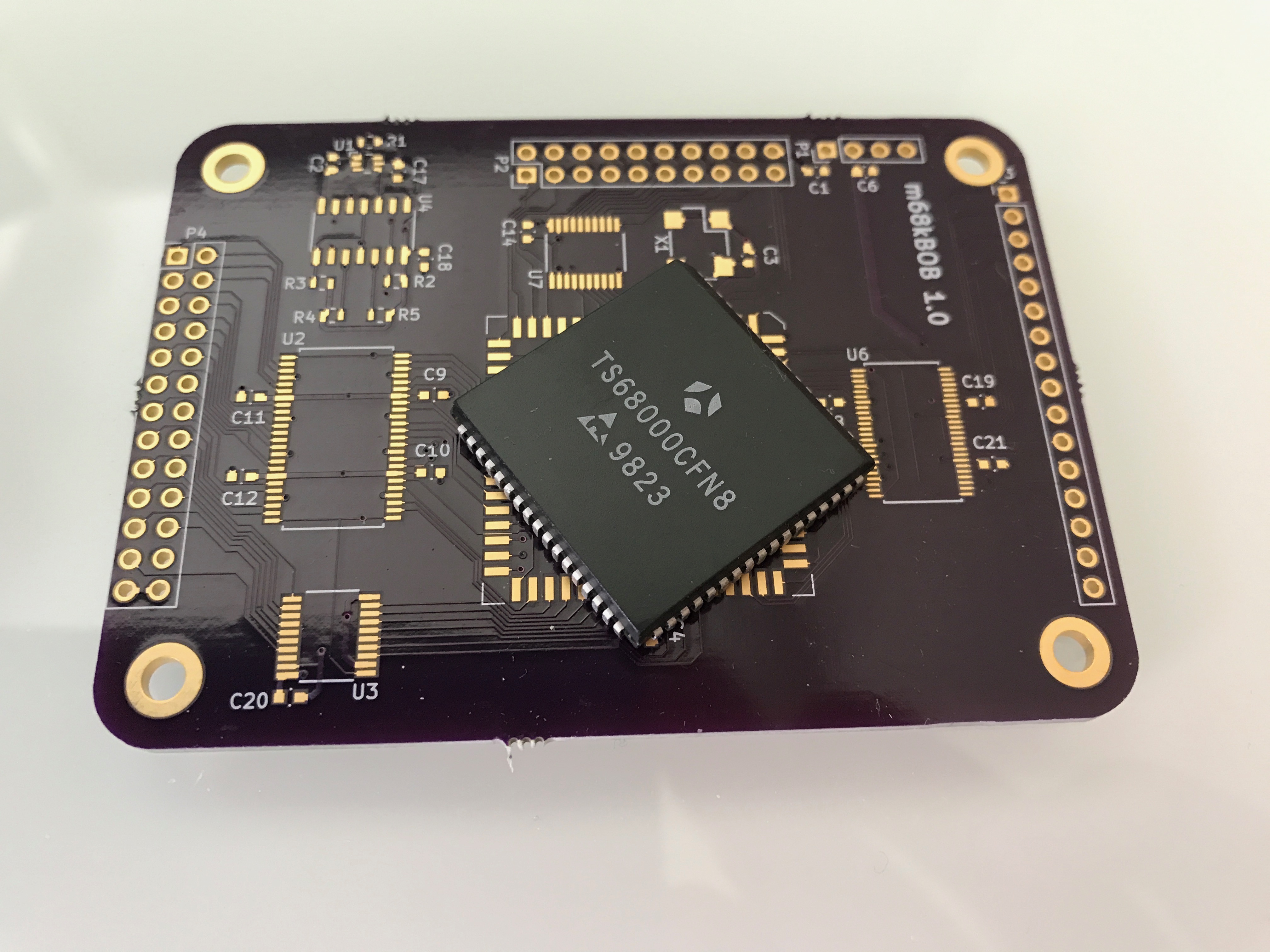
In phase one, I’ll wire up a 8MHz 68000 with 128k SRAM, SPI flash and an FPGA (Lattice Mach XO3), in phase 1a. The problems to solve is the 68k memory handshake, byte access to word-wide SRAM, and mirroring of flash in RAM. To get some sort of indication of success, I’ll also add a UART to the FPGA and write a message…

Phase 1b involves adding a VGA text mode over HDMI, and display text on it. The demo will be reading text from the UART and displaying on screen, and a challenge to keep up and scroll smoothly with the highest baudrates.

Phase 1c will replace the measly 128k SRAM with 16M EDO DRAM (maximum adressable memory for a plain 68000), witch requires an advanced EDO memory controller and a cache to take advantage of the EDO-ness.

At this point, it will be useful to write a boot monitor that can load user programs over the UART and execute to skip re-flasing the chip with a bus-pirate each time I want to test a new demo.

Phase 2 should probably focus on graphics and what that subsystem should look like. Plain framebuffer? Hardware sprites?

When I can display basic graphics, I should look into peripheral connectivity. I have this idea of adding an ESP32 module, wich would give WiFi Ethernet, and bluetooth hardware, and communicate with the rest of the PC over one or more SPI.

Audio is also important. There are plenty of classic audio chips implemented in FPGAs already, so why not have a couple of SID, an YM2149 and raw audio samples? Maybe throw in a classic Sound Blaster as well. Audio out should go both to HDMI and as analog out as well.

I’ll be back with some progress soon…

Kaboom!

One evening, daughter “K” was checking instagram. The phone was connected to a charger plugged into the wall socket. Suddenly there was a loud bang. With phone unplugged, the smelly charger was pulled from the scorched wall-socket.

Upon close examination, the charger wasn’t the Apple-charger it appeared to be. I decided to do a post-mortem to see how bad it was.

Irregardless of the burn-marks, it was really bad. Single-sided phenolic board, a simple discreet oscillator, a transformer and some passives. Oh, yes, an optocoupler provides feedback to the primary side.

In the designer’s defence, they did put some isolation distance between primary and secondary, except for the part where the secondary ground trace passes less than 0.5 mm from a trace that appears to be connected to a diode going from one mains terminal.


The source of the bang was the two transistors. The rightmost transistor lost a third of it’s case when the magic smoke left it in a hurry, while the left one fared a little better with just a burnt hole.

Designed by Appwy California, made by Flaxtronica? Not quite the genuine thing!

As a comparison, Ken Shirriff has made a teardown and analysis of a real Apple charger.

RedSub, part 2

Having sorted the basic shape and selected a driver, it’s time to pay attention to amplification.

The driver is rated for 120W continuous, with 180W peak, so an amplifier capable of about 200W should do fine. Since the amplifier will go inside the box, efficiency is important, even if the heatsink can stick out of the box in the back. Class D amplifiers are very popular, since they are compact relative to their power, are highly efficient, typically 80% – 90% and also provide high audio quality.

The last part isn’t really critical in a subwoofer, since the human ear isn’t particularly sensitive in the sub 120Hz region, but it would be pretty annoying to have the amplifier add distorsion above 120 Hz in a range where the speaker element can reproduce it, and even inaudible noise can damage the driver if it is strong enough.

After browsing the Internet for class D modules, I found quite a few based on the same chip, the IRS2092S  but with very different power ratings, even a 2500W monster. Something close to the reference design is available from countless sellers on eBay, costing from $15 – $30 (yes, identical boards!), with free shipping. They all come from Yuan Jing Audio, and all claim to use “Nikon” capacitors. (Yuan Jing themselves state that the capacitors are Nichicon, which is more likely, and may or may not be true.)

(Image from Yuan Jing)

Despite the module being 90% efficient, heat may become a problem in a 35l box. Also, the big caps (largish cans) are placed very close to the heatsink, and excessive heat will shorten their life significantly. If heat becomes a problem, there is one cure to try; putting the heatsink on the outside and moving the power transistor to the underside of the board. That might be a little tricky, since this module doesn’t use standard MOSFETs but a clever little half-bridge called IRFI4019. This half-bridge is part of the magic behind the performance of the audio module, and adding a couple of cm to the length of the pins on that 5-pin package may get it out of whack enough to start to oscillate, and fry  the expensive woofer element while emitting some serious RF energy. I’ll settle for monitoring the heat for now.

Another issue is the power supply. This YJ-module requires a symmetrical, ±30V – ±60V supply, while many other modules are happy with a positive supply only. There are a few options. One is to use a single 200W switcher with dual outputs, but that is pretty hard to find for a reasonable price, or two 100W switchers, which will drive up the price and size of the solution. Also, cheap chinese mains-powered stuff have a reputation for poor electrical safety… Leaves option three, a traditional linear, unregulated supply. All thats really needed is a transformer, a rectifier, a few fuses and some capacitors.

More about that in part #3.

Little Red Subwoofer

I’m very happy with my audio pro Addon Five. Except for one thing, bass.

I have decided to build a little red subwoofer for my home office. It should be small and compact, have active amplification, good low frequency response and decent sound quality. After a few iterations, I settled on a cube, 35x35x35 cm with an 8″ driver, and painted in Ferrari red to match the Addon fives.

Something like this…

The driver is the very nice Visaton TIW-200. It has a long stroke cone, +/- 12.5 mm and has proven it’s ability in my previous sub woofer project, the invisible BlueSub. (I might make a quick writeup about that one later)

Some simulation at micka.de suggests that it will have it’s -3dB point at about 34 Hz, while the Visaton data sheet states 32 Hz for a 30L box. RedSub will be about 35L, so I’ll have to measure the result and see for myself.

The black curve is an optimal vented box (82l) for the driver, blue is a closed box (38l) and red is the RedSub (35l).

DG/30: Problem!

Ett ljud man inte vill höra när man pluggar in strömmen i en gammal apparat är: “Pshshshshyyt!”. Det skulle kunna vara ljudet av den sista elektrolyten som kokar bort i torkad kondensator, typ.

Detta obehagliga ljud var det jag fick höra när jag skulle slå på min (som jag trodde) hela D211-terminal.

DG/30’an som denna skulle anslutas till surrade dock igång som den skulle. Hårddisken spann upp och båda status LED-arna tändes som de skulle på den. Detta är dock det enda jag vet ännu så länge, då ingen terminal verkar vilja vara med på noterna.

Det som jag trodde var en död terminal med urblekta namnskyltar visade sig ha produkt-id 6261-2, och vara en bildskärm med tangentbordsgenomgång. Hur denna ska anslutas får framtiden utvisa.